> ## Documentation Index
> Fetch the complete documentation index at: https://docs.solidyne.ar/llms.txt
> Use this file to discover all available pages before exploring further.
# MPX and Modulation
> MPX outputs configuration and FM modulation adjustment
## FM Output – MPX
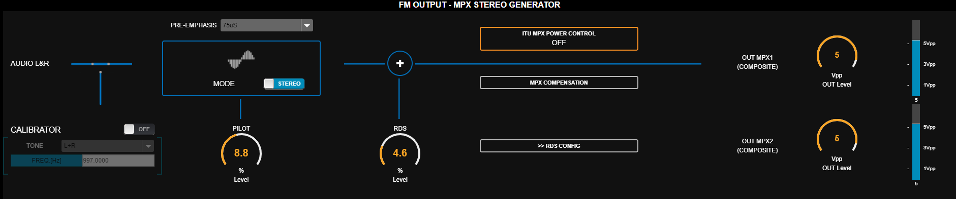
The **FM OUTPUT** menu configures the main transmission parameters:
1. **Levels** for stereo multiplex (MPX) signal outputs
2. Basic **RDS** configuration
3. **ITU BS.412** power control
 ### MPX Level
* Both MPX outputs have level control calibrated in **Vpp (peak-to-peak volts)**.
* Level is typically adjusted to achieve **100% modulation** at the transmitter.
* If the transmitter has MPX gain control, set the processor to **5 Vpp** and make fine adjustments at the transmitter.
### Pre-emphasis
Select the **pre-emphasis** curve according to your country's standard:
* 50 μs → Europe
* 75 μs → USA, Asia, Latin America
### Pilot Tone and RDS Carrier
* **PILOT**: pilot tone level → 9% (factory default).
* Can be increased up to **12%** in areas with high RF congestion.
* Higher pilot/RDS levels reduce audio loudness for a given modulation level.
* **MODE**: switches transmission between **STEREO** and **MONO**. In MONO mode, the pilot is suppressed and MPX signal is monaural. Switching can be done:
* Through **configuration** (fixed in system).
* **Preset forced** → Presets have a variable to switch to mono (see *Preset Manager*). In this case control will show *"Forced to MONO by preset"*.
* **Remotely** using **542 Lite Commander** application *(requires external computer and IP remote access).*
See [**About MONO transmission**](/en/542/542-mono)
* **RDS**: RDS subcarrier modulation → 4% (factory default).
### MPX Output Compensation
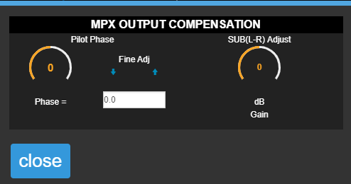
* **Pilot Phase**: fine pilot phase adjustment. Improves stereo separation.
* **SUB(L-R) adjust**: adjusts L-R module level to compensate for coaxial/antenna system mismatches.
### MPX Level
* Both MPX outputs have level control calibrated in **Vpp (peak-to-peak volts)**.
* Level is typically adjusted to achieve **100% modulation** at the transmitter.
* If the transmitter has MPX gain control, set the processor to **5 Vpp** and make fine adjustments at the transmitter.
### Pre-emphasis
Select the **pre-emphasis** curve according to your country's standard:
* 50 μs → Europe
* 75 μs → USA, Asia, Latin America
### Pilot Tone and RDS Carrier
* **PILOT**: pilot tone level → 9% (factory default).
* Can be increased up to **12%** in areas with high RF congestion.
* Higher pilot/RDS levels reduce audio loudness for a given modulation level.
* **MODE**: switches transmission between **STEREO** and **MONO**. In MONO mode, the pilot is suppressed and MPX signal is monaural. Switching can be done:
* Through **configuration** (fixed in system).
* **Preset forced** → Presets have a variable to switch to mono (see *Preset Manager*). In this case control will show *"Forced to MONO by preset"*.
* **Remotely** using **542 Lite Commander** application *(requires external computer and IP remote access).*
See [**About MONO transmission**](/en/542/542-mono)
* **RDS**: RDS subcarrier modulation → 4% (factory default).
### MPX Output Compensation
* **Pilot Phase**: fine pilot phase adjustment. Improves stereo separation.
* **SUB(L-R) adjust**: adjusts L-R module level to compensate for coaxial/antenna system mismatches.
 See **Channel Separation Measurement and Adjustment**
### ITU BS.412 Power Control
Stage that regulates MPX signal power according to **ITU-R BS.412** recommendation.\
Mainly applicable in **Europe**.
If your country's regulations do not require BS.412, do not activate this control.\
It will unnecessarily reduce on-air loudness.
* Sets a limit on **average MPX energy** (60 sec window), maintaining maximum modulation at 75 kHz.
* Aims to reduce interference between stations with 100 kHz spacing.
* Reference standard: **0 dBr** with +0.2 dB tolerance.
See **Channel Separation Measurement and Adjustment**
### ITU BS.412 Power Control
Stage that regulates MPX signal power according to **ITU-R BS.412** recommendation.\
Mainly applicable in **Europe**.
If your country's regulations do not require BS.412, do not activate this control.\
It will unnecessarily reduce on-air loudness.
* Sets a limit on **average MPX energy** (60 sec window), maintaining maximum modulation at 75 kHz.
* Aims to reduce interference between stations with 100 kHz spacing.
* Reference standard: **0 dBr** with +0.2 dB tolerance.
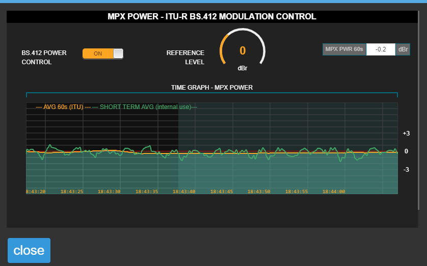 The **ITU BS.412 modulation** control modifies the MPX power reference level.\
The time graph shows MPX power evolution over a 120-second window.\
The graph presents a 60-second integration curve as established by BS.412; and a short-time integration profile.
**Processing Presets and BS.412**
Any processing preset can be used with MPX power control active.\
Factory presets include optimized adjustments for ITU BS.412 operation.
With a power limit in place, using high-loudness presets makes no sense, as audio would be processed to increase loudness only to decrease it later. One advantage of ITU BS.412 regulation is that stations can use more dynamic range.
## FM Modulation Adjustment
Factory default settings are **9%** for pilot tone and **4%** for RDS carrier.\
Usually these values don't need modification. If changes are required, make them BEFORE adjusting modulation.
Adjustment steps:
1. Turn on the **CALIBRATOR** in the **FM OUTPUT** screen → a 400 Hz tone replaces the input signal.
2. Tune the transmission on the internal receiver and verify 100% modulation on the processor's modulation indicator.
* Fine adjustment → modify MPX level (default: 5 Vpp).
The 542's modulation indicator measures with **fast integration** of 125 uS (adjustable 0 to 1 ms).\
Transmitters with slow meters may show different values with program material.\
Due to slow integration, the transmitter's indicator will be unable to show peaks. In this case, measurement will be more similar with higher program material peak density.
Measurement on the 542 is only valid with **optimal reception** on the tuner.
3. Turn off the **CALIBRATOR** → program signal returns to calibrated level.
### About Modulation Peaks
* Many countries follow FCC (USA) standards → Recommendation 73.268.
* **Slight overshoots** are allowed on infrequent peaks *("In no case is it to exceed 100 % on peaks of frequent recurrence")*
* The 542APC complies with this standard, enabling this tolerance.
### Stereo Separation Measurement and Adjustment
Channel separation can be affected by losses in the coaxial-antenna system. 1\
542APC includes **pilot tone phase** and **(L-R) module gain** adjustments that can partially compensate for transmission system non-linearity, improving channel separation.
> *(1) FM stereo separation degradation as a function of antena system VSWR*,\
> by Peter Onnigian, Jampro Antenna Company, for the 31st AES convention.
Adjustment procedure:
1. On the **FM Monitor Analyzer** screen, measure channel separation.\
Higher dB numbers indicate better separation.\
If reading is above 40 dB (Excellent), no adjustments are needed.
Measurement introduces **brief audible tones on-air**.\
Proper station tuning is essential for valid measurements.
2. On **FM OUTPUT** screen open **MPX COMPENSATION** option
3. Increase "**SUB(L-R) Adjust**" by 0.1 dB.
4. Repeat channel separation measurement and verify if value improved over previous measurement.
* If separation increased → return to step 3, increasing again by **0.1 dB** and repeating measurement.
* Continue until separation no longer improves.
5. If separation decreases instead of improving, reduce **SUB(L-R) Adjust** by **0.2 dB**.
6. Measure separation again.
* Verify improvement.
* Repeat in **0.1 dB** steps until best possible value is achieved.
7. If **Excellent** value is still not reached, try adjusting **Pilot Phase** control in **0.5°** steps, first one way then the other, to check for additional improvement.
8. Once best possible value is achieved (with good transmitters and antennas should be **Excellent >40 dB**), save adjustment to internal memory by pressing **SAVE** in left menu.
* If not saved, adjustment is lost when processor restarts.
Values above **40 dB** are not measured, as it's proven that human hearing (even using headphones) cannot perceive improvements in stereo space sensation beyond this point.
The **ITU BS.412 modulation** control modifies the MPX power reference level.\
The time graph shows MPX power evolution over a 120-second window.\
The graph presents a 60-second integration curve as established by BS.412; and a short-time integration profile.
**Processing Presets and BS.412**
Any processing preset can be used with MPX power control active.\
Factory presets include optimized adjustments for ITU BS.412 operation.
With a power limit in place, using high-loudness presets makes no sense, as audio would be processed to increase loudness only to decrease it later. One advantage of ITU BS.412 regulation is that stations can use more dynamic range.
## FM Modulation Adjustment
Factory default settings are **9%** for pilot tone and **4%** for RDS carrier.\
Usually these values don't need modification. If changes are required, make them BEFORE adjusting modulation.
Adjustment steps:
1. Turn on the **CALIBRATOR** in the **FM OUTPUT** screen → a 400 Hz tone replaces the input signal.
2. Tune the transmission on the internal receiver and verify 100% modulation on the processor's modulation indicator.
* Fine adjustment → modify MPX level (default: 5 Vpp).
The 542's modulation indicator measures with **fast integration** of 125 uS (adjustable 0 to 1 ms).\
Transmitters with slow meters may show different values with program material.\
Due to slow integration, the transmitter's indicator will be unable to show peaks. In this case, measurement will be more similar with higher program material peak density.
Measurement on the 542 is only valid with **optimal reception** on the tuner.
3. Turn off the **CALIBRATOR** → program signal returns to calibrated level.
### About Modulation Peaks
* Many countries follow FCC (USA) standards → Recommendation 73.268.
* **Slight overshoots** are allowed on infrequent peaks *("In no case is it to exceed 100 % on peaks of frequent recurrence")*
* The 542APC complies with this standard, enabling this tolerance.
### Stereo Separation Measurement and Adjustment
Channel separation can be affected by losses in the coaxial-antenna system. 1\
542APC includes **pilot tone phase** and **(L-R) module gain** adjustments that can partially compensate for transmission system non-linearity, improving channel separation.
> *(1) FM stereo separation degradation as a function of antena system VSWR*,\
> by Peter Onnigian, Jampro Antenna Company, for the 31st AES convention.
Adjustment procedure:
1. On the **FM Monitor Analyzer** screen, measure channel separation.\
Higher dB numbers indicate better separation.\
If reading is above 40 dB (Excellent), no adjustments are needed.
Measurement introduces **brief audible tones on-air**.\
Proper station tuning is essential for valid measurements.
2. On **FM OUTPUT** screen open **MPX COMPENSATION** option
3. Increase "**SUB(L-R) Adjust**" by 0.1 dB.
4. Repeat channel separation measurement and verify if value improved over previous measurement.
* If separation increased → return to step 3, increasing again by **0.1 dB** and repeating measurement.
* Continue until separation no longer improves.
5. If separation decreases instead of improving, reduce **SUB(L-R) Adjust** by **0.2 dB**.
6. Measure separation again.
* Verify improvement.
* Repeat in **0.1 dB** steps until best possible value is achieved.
7. If **Excellent** value is still not reached, try adjusting **Pilot Phase** control in **0.5°** steps, first one way then the other, to check for additional improvement.
8. Once best possible value is achieved (with good transmitters and antennas should be **Excellent >40 dB**), save adjustment to internal memory by pressing **SAVE** in left menu.
* If not saved, adjustment is lost when processor restarts.
Values above **40 dB** are not measured, as it's proven that human hearing (even using headphones) cannot perceive improvements in stereo space sensation beyond this point.