> ## Documentation Index
> Fetch the complete documentation index at: https://docs.solidyne.ar/llms.txt
> Use this file to discover all available pages before exploring further.
# Connection Diagrams
> Rear Panel Description and Connection Diagrams
## Power Supply
The DX816/822 operates with an external power supply. It includes a **switching power supply 90-240 V**, which works with any electrical grid, even in areas with significant voltage fluctuations. It delivers **regulated 28 VDC**.
The rear panel features the **DC IN** power input, with a **2.1 mm** center-positive barrel connector.
It is recommended to always use the **original power supply provided by Solidyne**.
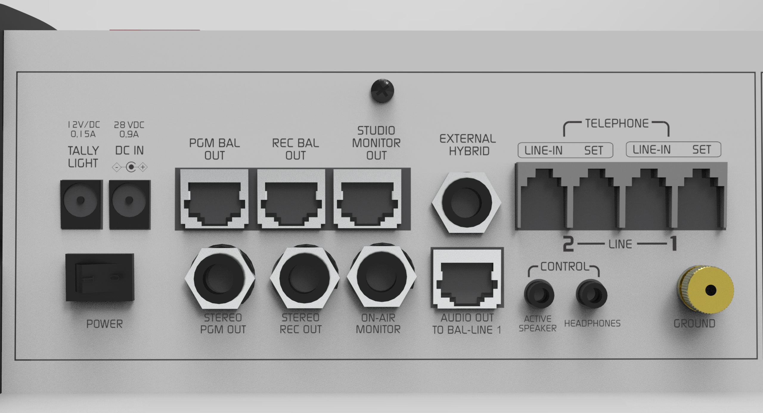 The Tally Light barrel connector supplies voltage for the "On-Air" light. This connector uses a 2.5 mm pin to prevent accidental connection of the power supply.
## Grounding
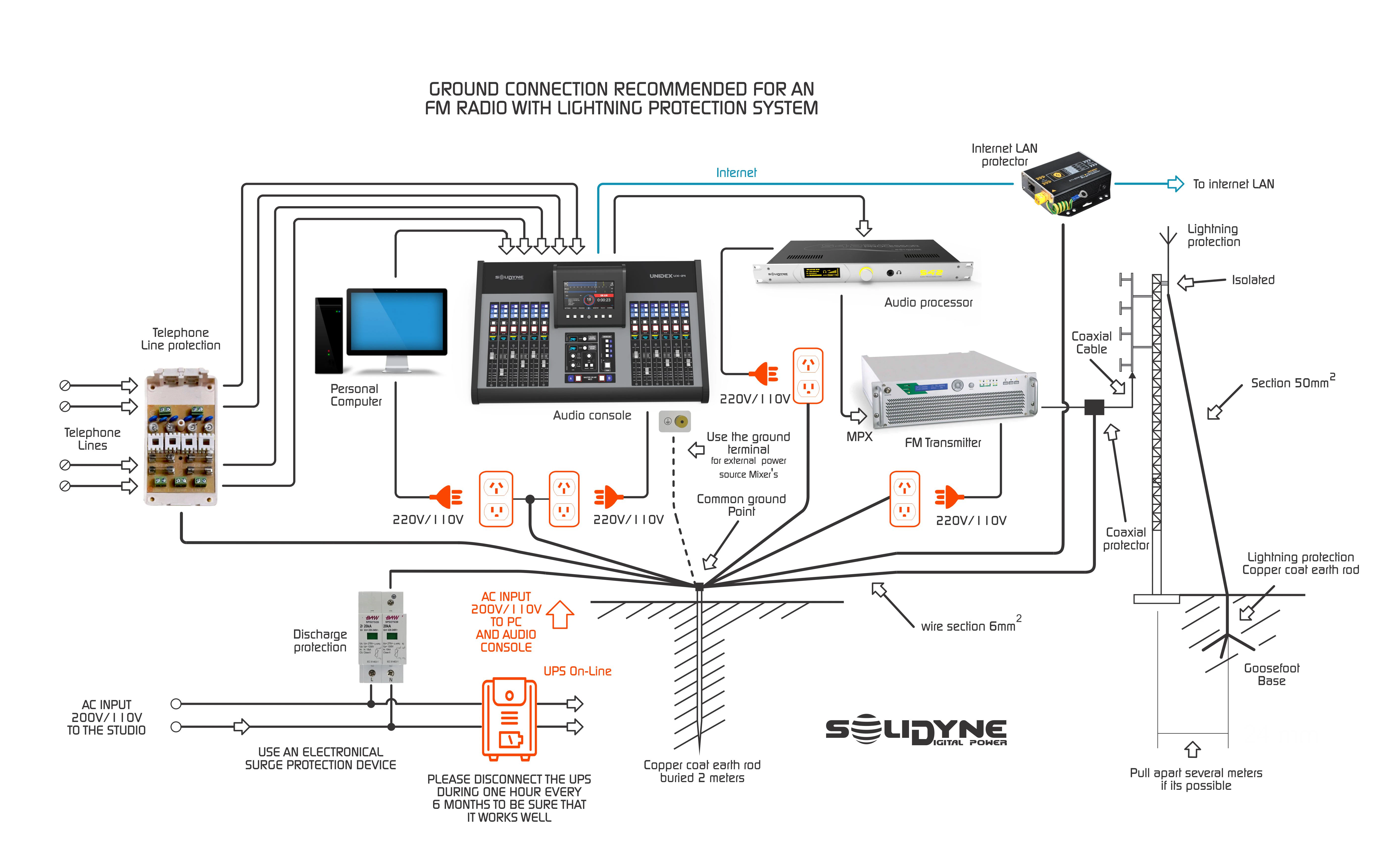
Grounding is accomplished through a **bronze terminal** that ensures chassis grounding. Use **2 mm gauge** wire connected to a **buried copper ground rod**.
### General recommendation for grounding and protection
To prevent equipment damage, appropriate grounding and protection measures must be implemented on Internet and telephone lines. The warranty does not cover damage caused by lightning strikes, power surges, or electrical grid failures.
The Tally Light barrel connector supplies voltage for the "On-Air" light. This connector uses a 2.5 mm pin to prevent accidental connection of the power supply.
## Grounding
Grounding is accomplished through a **bronze terminal** that ensures chassis grounding. Use **2 mm gauge** wire connected to a **buried copper ground rod**.
### General recommendation for grounding and protection
To prevent equipment damage, appropriate grounding and protection measures must be implemented on Internet and telephone lines. The warranty does not cover damage caused by lightning strikes, power surges, or electrical grid failures.
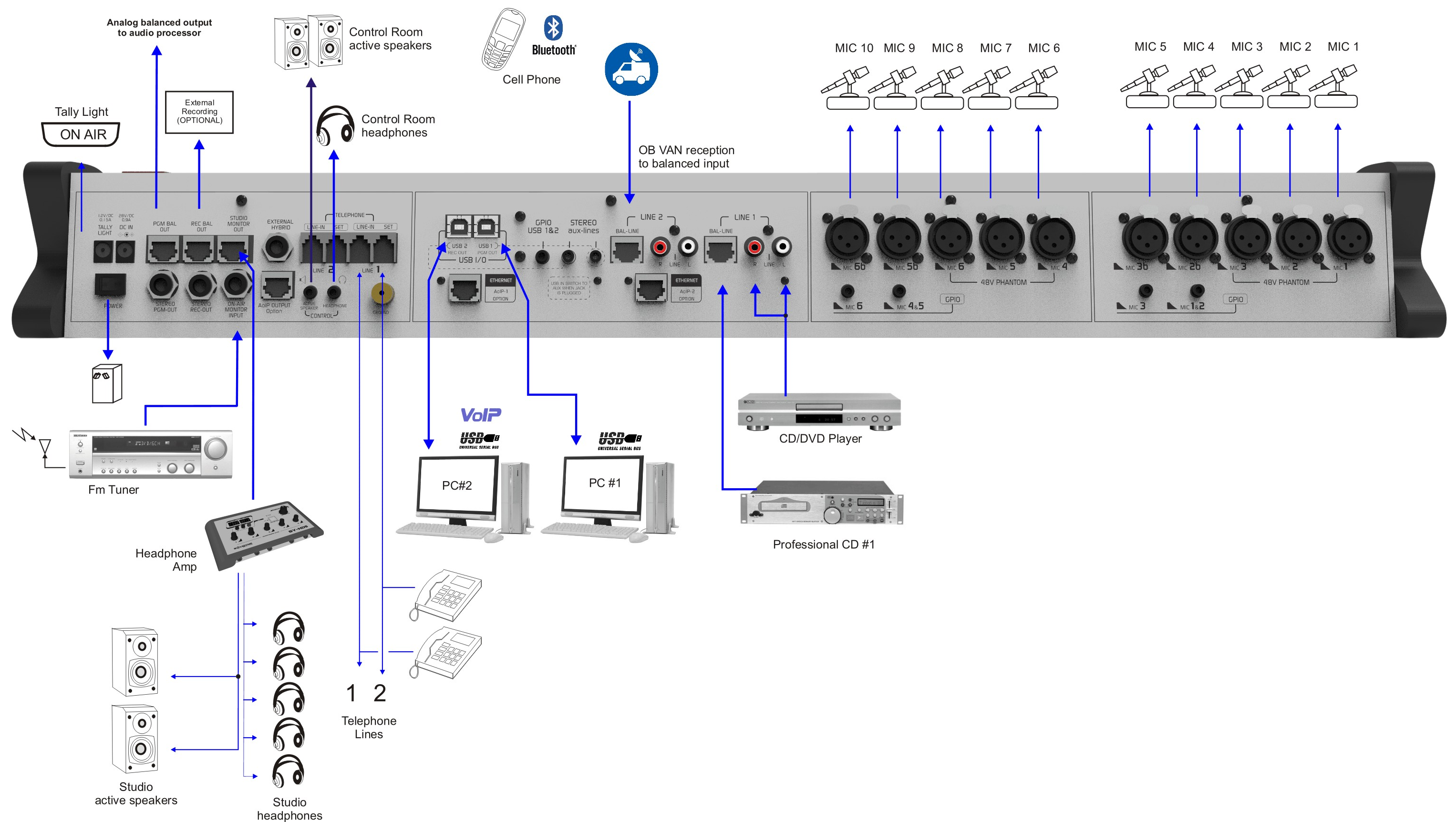
 ## General Connection Diagram (DX822)
The general connection diagram shows the rear panel of the DX822 model. \
The DX816 model is identical, except for the microphone inputs which are five.
## General Connection Diagram (DX822)
The general connection diagram shows the rear panel of the DX822 model. \
The DX816 model is identical, except for the microphone inputs which are five.
 ***
## About RJ45 Connectors
With the advent of **audio over IP (AoIP)**, various manufacturers including us have adopted the use of **RJ45 connectors** and shielded multipair cable to replace traditional audio connectors.
* A single RJ45 connector contains **two balanced lines**, reducing the size of the rear panel and the number of connectors.
* The use of **structured cabling** simplifies installation between distant equipment anywhere in the world, thanks to the wide availability of components and assembly tools used in data networks.
* Soldering is eliminated, simplifying and speeding up wiring.
At the multipair cable end, the connection to audio devices (microphones, speakers, interfaces) still uses **standard audio connectors**.\
For this purpose, RJ45 runs terminate in balanced connectors appropriate for the destination equipment.
The balanced inputs on the **Solidyne DX816/822** console use **RJ45 connectors** and are wired with shielded **CAT-5 (STP)** multipair cable.
The **Solidyne MNGX816** connection kit includes all necessary cables for balanced inputs and outputs with RJ45, ensuring reliability and preventing connection errors.
Solidyne's RJ45 audio connections are **compatible with those provided by StudioHub** ([www.studiohub.com](http://www.studiohub.com)).
***
## About RJ45 Connectors
With the advent of **audio over IP (AoIP)**, various manufacturers including us have adopted the use of **RJ45 connectors** and shielded multipair cable to replace traditional audio connectors.
* A single RJ45 connector contains **two balanced lines**, reducing the size of the rear panel and the number of connectors.
* The use of **structured cabling** simplifies installation between distant equipment anywhere in the world, thanks to the wide availability of components and assembly tools used in data networks.
* Soldering is eliminated, simplifying and speeding up wiring.
At the multipair cable end, the connection to audio devices (microphones, speakers, interfaces) still uses **standard audio connectors**.\
For this purpose, RJ45 runs terminate in balanced connectors appropriate for the destination equipment.
The balanced inputs on the **Solidyne DX816/822** console use **RJ45 connectors** and are wired with shielded **CAT-5 (STP)** multipair cable.
The **Solidyne MNGX816** connection kit includes all necessary cables for balanced inputs and outputs with RJ45, ensuring reliability and preventing connection errors.
Solidyne's RJ45 audio connections are **compatible with those provided by StudioHub** ([www.studiohub.com](http://www.studiohub.com)).