> ## Documentation Index
> Fetch the complete documentation index at: https://docs.solidyne.ar/llms.txt
> Use this file to discover all available pages before exploring further.
# UDX 2TEL Adapter
> Two-line telephone hybrid (POTS)
## Overview
The **UDX 2TEL** interface allows connection of **two analog phone lines** (POTS) and their associated telephone sets.
* **UDX 2TEL-P**\
Includes controls to **take the line** and **transfer it to the console**.\
This allows installing the unit and associated phones in locations away from the console, such as a production office.
* **UDX 2TEL**\
Has no onboard controls.\
Designed for calls to be handled by the operator from the console.
All communication functions (dialing, answering, holding, preview talk) are operated **from the console**.\
At the mixer, each telephone line works **independently** on a channel.
***
## UDX 2TEL Connection
Connection is made with two standard **STP RJ45–RJ45** cables connected **pin-to-pin** (Solidyne **SOL-P50** or **SOL-P25**).
* **"TO UNIDEX INPUT" output** → Connect to a **UNIDEX input** (1 to 4)
* **"FROM UNIDEX OUTPUT" input** → Connect to an **unbalanced analog output** (5 to 8)
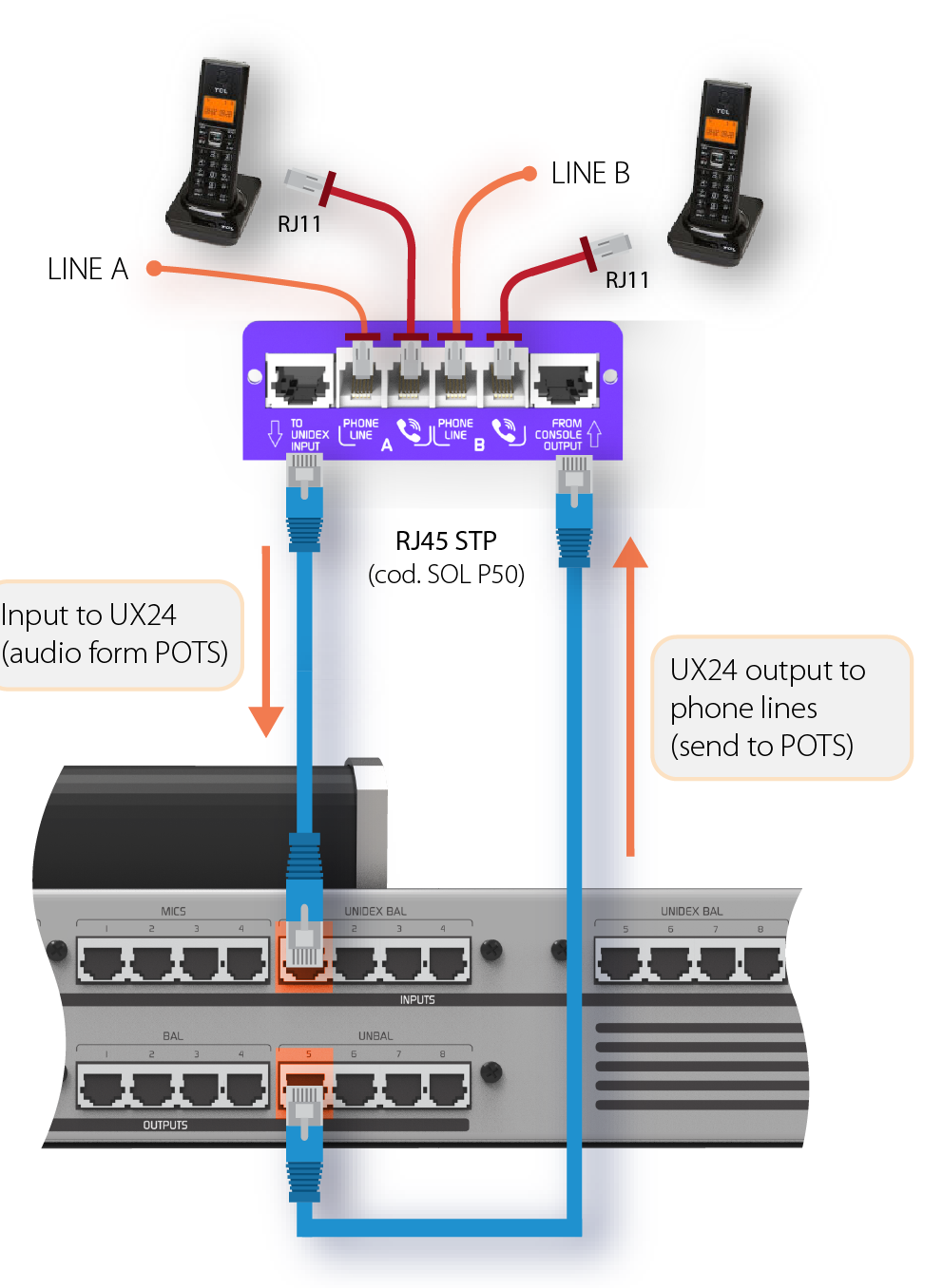 On the console's rear panel, **UNIDEX inputs 1, 2, 3 and 4** are aligned with unbalanced outputs **5, 6, 7 and 8** to simplify wiring.
### Recommended input/output correspondence
| UNIDEX Input | Unbalanced Output |
| -----------: | ----------------- |
| UNIDEX 1 | UNBAL 5 |
| UNIDEX 2 | UNBAL 6 |
| UNIDEX 3 | UNBAL 7 |
| UNIDEX 4 | UNBAL 8 |
## Telephone Line Connection
Telephone lines and their associated sets are connected using standard **RJ11** cables.
* Two inputs for **telephone lines**
* Two inputs for connecting **associated telephone sets**
The telephones work normally when the lines are **not seized by the console**.
If there is **no dial tone** when taking the phone line, verify that the **LINE** and **TELEPHONE** connections are not reversed on the **UDX TEL** adapter.
### Connection Type
* Lines can be connected directly to the **public telephone network** or to the station's **PBX**.
* Private exchanges (**PBX**) slightly reduce hybrid rejection, so direct connection to the **public network** is recommended.
* **GSM ATA** adapters (cellular gateway) can be used, which work with a GSM chip and allow connection to a conventional fixed telephone.
### Protection and Filtering
**UDX TEL** adapters include:
* Internal **RF** rejection filters (AM, VHF and UHF bands)
* Internal protection against high voltage surges (indirect lightning) using metal oxide varistors.
Telephone lines have internal protection against high voltage surges (indirect lightning) using **metal oxide varistors**. However, it is **essential** to install **external gas discharge tubes** on public network lines, connected to a **2m buried ground rod**.
In case of lightning damage, **equipment warranty does not cover repairs**.\
Consult the **General Ground Connection Diagram** for proper installation.
Once the **UDX 2TEL** (or **TEL+BT**) adapter is connected, configure:
* **Inputs**
* **Outputs (sends)**
* **Channels**
## Input Configuration
The layout and shape of controls shown below may vary. This does not affect the configuration procedure.
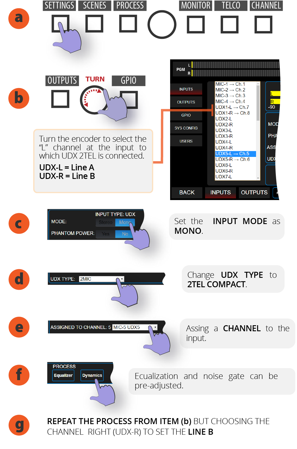
1. On the main screen, access **SETTINGS**.
2. **Turn the encoder** to select the **"L" channel** of the UNIDEX input where UDX 2TEL is connected. "L" corresponds to LINE A of UDX 2MIC while "R" is LINE B.
3. By touching the screen, set **INPUT MODE** to **MONO**.
4. In **UDX TYPE** option select **2TEL**
5. Touch the screen to open the **ASSIGNED TO CHANNEL** menu to assign a CHANNEL to the input. If you choose a channel that already has an input assigned, a warning will appear. If you continue, the input on that channel is replaced.
It is recommended to assign TELCO lines to physical channels.
6. In the **PROCESS** section you can preset equalization and/or noise gate.
7. Press BACK to return to main screen.
8. The next step will be configuring the output.
On the console's rear panel, **UNIDEX inputs 1, 2, 3 and 4** are aligned with unbalanced outputs **5, 6, 7 and 8** to simplify wiring.
### Recommended input/output correspondence
| UNIDEX Input | Unbalanced Output |
| -----------: | ----------------- |
| UNIDEX 1 | UNBAL 5 |
| UNIDEX 2 | UNBAL 6 |
| UNIDEX 3 | UNBAL 7 |
| UNIDEX 4 | UNBAL 8 |
## Telephone Line Connection
Telephone lines and their associated sets are connected using standard **RJ11** cables.
* Two inputs for **telephone lines**
* Two inputs for connecting **associated telephone sets**
The telephones work normally when the lines are **not seized by the console**.
If there is **no dial tone** when taking the phone line, verify that the **LINE** and **TELEPHONE** connections are not reversed on the **UDX TEL** adapter.
### Connection Type
* Lines can be connected directly to the **public telephone network** or to the station's **PBX**.
* Private exchanges (**PBX**) slightly reduce hybrid rejection, so direct connection to the **public network** is recommended.
* **GSM ATA** adapters (cellular gateway) can be used, which work with a GSM chip and allow connection to a conventional fixed telephone.
### Protection and Filtering
**UDX TEL** adapters include:
* Internal **RF** rejection filters (AM, VHF and UHF bands)
* Internal protection against high voltage surges (indirect lightning) using metal oxide varistors.
Telephone lines have internal protection against high voltage surges (indirect lightning) using **metal oxide varistors**. However, it is **essential** to install **external gas discharge tubes** on public network lines, connected to a **2m buried ground rod**.
In case of lightning damage, **equipment warranty does not cover repairs**.\
Consult the **General Ground Connection Diagram** for proper installation.
Once the **UDX 2TEL** (or **TEL+BT**) adapter is connected, configure:
* **Inputs**
* **Outputs (sends)**
* **Channels**
## Input Configuration
The layout and shape of controls shown below may vary. This does not affect the configuration procedure.
1. On the main screen, access **SETTINGS**.
2. **Turn the encoder** to select the **"L" channel** of the UNIDEX input where UDX 2TEL is connected. "L" corresponds to LINE A of UDX 2MIC while "R" is LINE B.
3. By touching the screen, set **INPUT MODE** to **MONO**.
4. In **UDX TYPE** option select **2TEL**
5. Touch the screen to open the **ASSIGNED TO CHANNEL** menu to assign a CHANNEL to the input. If you choose a channel that already has an input assigned, a warning will appear. If you continue, the input on that channel is replaced.
It is recommended to assign TELCO lines to physical channels.
6. In the **PROCESS** section you can preset equalization and/or noise gate.
7. Press BACK to return to main screen.
8. The next step will be configuring the output.
 ## Output Configuration
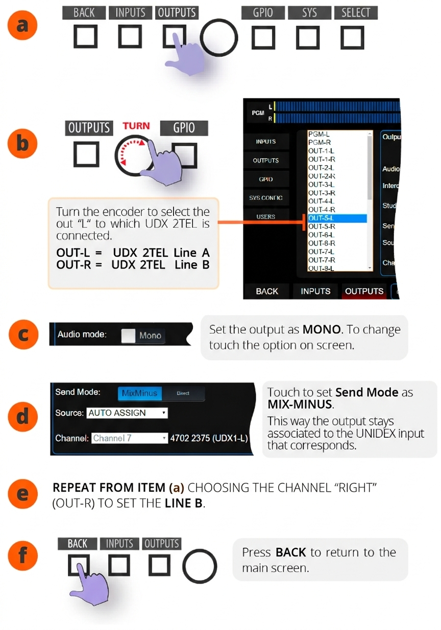
1. From the main screen, access **SETTINGS**.
2. In SETTINGS choose **OUTPUTS**.
3. Turn the encoder to select "L" channel of the output where UDX 2TEL is connected.
OUT-L = UDX 2TEL Line A
OUT-R = UDX 2TEL Line B
4. In **AUDIO MODE**, set the output to **MONO**.
5. Set **SEND MODE** to **MIX-MINUS**. When activating MIX-MINUS the output will be associated with its corresponding UNIDEX input.
6. Repeat the operation for Line B.
The **send level** to the line (OUT GAIN) and **input gain** can be adjusted **during operation** from the TELCO screen.
## Output Configuration
1. From the main screen, access **SETTINGS**.
2. In SETTINGS choose **OUTPUTS**.
3. Turn the encoder to select "L" channel of the output where UDX 2TEL is connected.
OUT-L = UDX 2TEL Line A
OUT-R = UDX 2TEL Line B
4. In **AUDIO MODE**, set the output to **MONO**.
5. Set **SEND MODE** to **MIX-MINUS**. When activating MIX-MINUS the output will be associated with its corresponding UNIDEX input.
6. Repeat the operation for Line B.
The **send level** to the line (OUT GAIN) and **input gain** can be adjusted **during operation** from the TELCO screen.
 ## Channel Configuration
1. On main screen, press **CHANNEL**. CUE buttons change to SELECT mode.
2. Press the **CUE/SELECT** button on the channel to configure. The console exits SELECT mode and shows the CHANNEL screen for the selected channel.
3. In **MODE** option, open the menu and choose **TELCO**.
4. To edit the **label**, touch the name. An on-screen keyboard will appear to enter text.
5. Verify that the output assignment indicates the output corresponding to the input used, and that the mode is MIX-MINUS.
6. Press BACK to return to main screen.
TO PERMANENTLY STORE THE SETTINGS, **SAVE THE SCENE**.
## Null Adjustment
It is essential to adjust the **rejection factor** or *null* for each telephone line.
* From factory, units are calibrated to work with **ideal impedances**.
* In practice, real lines present impedance variations.
* If rejection is not optimized, when putting a call on air, the studio announcer's voice can mix with the call audio, degrading quality.
This adjustment applies to:
* **UDX 2TEL**
* **UDX 2TEL-P**
* **TEL+BT** (landline only)
### Adjustment Procedure
1. Press **TELCO** button to access Telecommunications operation screen.
2. Establish a call (can be outgoing or incoming). The telephone microphone should be muted on the other end.
3. In the **CONFIG** section of TELCO screen press ENTER **Null Adjust**. The console injects an adjustment tone into the telephone line. The return level is displayed in INPUT LEVEL.
The line does not need to be on air (the fader can be closed).
4. Rejection is adjusted from the UDX 2TEL box. Each line has an adjustment preset.
5. Using a trimmer tool, gently turn the preset in both directions until finding the point where the signal return shown on the indicator is minimum.
6. Once rejection is adjusted, end the call.
7. Repeat the rejection adjustment for the other line.
If you change telephone lines, the adjustment must be repeated.
## Channel Configuration
1. On main screen, press **CHANNEL**. CUE buttons change to SELECT mode.
2. Press the **CUE/SELECT** button on the channel to configure. The console exits SELECT mode and shows the CHANNEL screen for the selected channel.
3. In **MODE** option, open the menu and choose **TELCO**.
4. To edit the **label**, touch the name. An on-screen keyboard will appear to enter text.
5. Verify that the output assignment indicates the output corresponding to the input used, and that the mode is MIX-MINUS.
6. Press BACK to return to main screen.
TO PERMANENTLY STORE THE SETTINGS, **SAVE THE SCENE**.
## Null Adjustment
It is essential to adjust the **rejection factor** or *null* for each telephone line.
* From factory, units are calibrated to work with **ideal impedances**.
* In practice, real lines present impedance variations.
* If rejection is not optimized, when putting a call on air, the studio announcer's voice can mix with the call audio, degrading quality.
This adjustment applies to:
* **UDX 2TEL**
* **UDX 2TEL-P**
* **TEL+BT** (landline only)
### Adjustment Procedure
1. Press **TELCO** button to access Telecommunications operation screen.
2. Establish a call (can be outgoing or incoming). The telephone microphone should be muted on the other end.
3. In the **CONFIG** section of TELCO screen press ENTER **Null Adjust**. The console injects an adjustment tone into the telephone line. The return level is displayed in INPUT LEVEL.
The line does not need to be on air (the fader can be closed).
4. Rejection is adjusted from the UDX 2TEL box. Each line has an adjustment preset.
5. Using a trimmer tool, gently turn the preset in both directions until finding the point where the signal return shown on the indicator is minimum.
6. Once rejection is adjusted, end the call.
7. Repeat the rejection adjustment for the other line.
If you change telephone lines, the adjustment must be repeated.