> ## Documentation Index
> Fetch the complete documentation index at: https://docs.solidyne.ar/llms.txt
> Use this file to discover all available pages before exploring further.
# Monitor wiring
> Studio monitoring wiring
## STUDIO MONITOR Output Connector
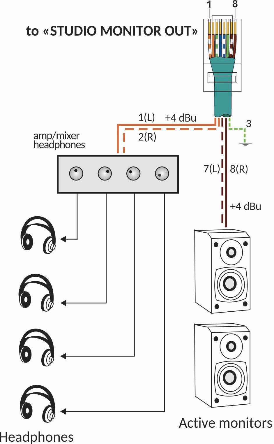
The **STUDIO MONITOR** output connector carries the monitoring signals to the main studio (Studio A).
**Solidyne StudioBox HD3 and HD5** monitoring bays connect directly to this output using an **RJ45–RJ45 STP** cable with **pin-to-pin** connection.
When not using a StudioBox, the console includes an **RJ45 to audio connectors** adapter cable, allowing direct connection of active speakers and headphone distributors in the studio.
The **STUDIO MONITOR** output must not be connected using cables other than the original or through generic RJ45 adapter sections. This can cause failures or damage to the Studio Monitor output.
The signals present in the **STUDIO MONITOR** connector are:
| **PIN** | **SIGNAL** |
| :-----: | ------------------------ |
| 1 | Headphones Left (+4 dBu) |
| 2 | Headphones Right |
| 3 | GND |
| 4 | ON-AIR (+14 V) |
| 5 | Talkback to Control Room |
| 6 | VCC +14 V |
| 7 | Speakers Left (+4 dBu) |
| 8 | Speakers Right |
| | \*Chassis = GND |
 ***
**STUDIO B on UX24**
To configure a monitoring circuit in a second studio, assign one of the general outputs, configured to be **muted** when Studio B is active.
***
**STUDIO B on UX24**
To configure a monitoring circuit in a second studio, assign one of the general outputs, configured to be **muted** when Studio B is active.