> ## Documentation Index
> Fetch the complete documentation index at: https://docs.solidyne.ar/llms.txt
> Use this file to discover all available pages before exploring further.
# GPIO and Tally Light
> External device control via GPIO in UNIDEX
## GPIO Control
The **GPIO** connector *(General Purpose Input/Output)* provides inputs and outputs that allow controlling console functions (GPI) such as mic activation; or controlling external devices (GPO) like tally lights or audio processing.
* **GPI** supports trigger signals of **5-15V/150mA** (high active).
* **GPO 1 to 7** are *"open drain"* type. They work as switches, connecting the output to ground. They support signals of **5–24 V / 250 mA**.
* **PIN 8** provides **DC voltage** (varies by console model, see below). It can be used to directly trigger GPIs (with a switch). Or to power an external device controlled through a GPO (for example a light or small relay)
## Pin-out and configuration
### DB15 PIN-OUT (UX24)
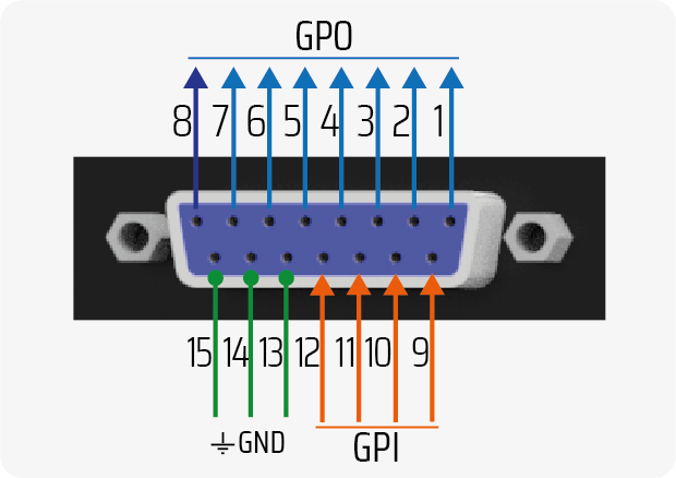 **GPO 8** provides **+12V / 250 mA** when active. 0V when inactive.
### ACTION CONFIGURATION
**GPO 8** provides **+12V / 250 mA** when active. 0V when inactive.
### ACTION CONFIGURATION
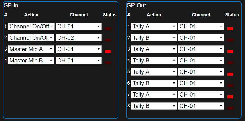 GPIO-triggered actions are defined in the `SETTINGS→GPIO` screen. Each **GP-IN** and **GP-OUT** can be associated with a channel and a specific action.
Available actions for **GPI** are:
`UNASSIGNED; CHANNEL ON/OFF; CHANNEL MUTE; MASTER MIC A; MASTER MIC B`
Available actions for **GPO** are:
`UNASSIGNED; CHANNEL ON/OFF; TALLY A; TALLY B; TELCO RING; OUTPUT +12V` (GPO8 only)
### DB15 PIN-OUT (UX18)
GPIO-triggered actions are defined in the `SETTINGS→GPIO` screen. Each **GP-IN** and **GP-OUT** can be associated with a channel and a specific action.
Available actions for **GPI** are:
`UNASSIGNED; CHANNEL ON/OFF; CHANNEL MUTE; MASTER MIC A; MASTER MIC B`
Available actions for **GPO** are:
`UNASSIGNED; CHANNEL ON/OFF; TALLY A; TALLY B; TELCO RING; OUTPUT +12V` (GPO8 only)
### DB15 PIN-OUT (UX18)
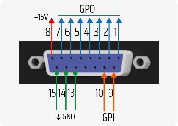 **PIN 8** PROVIDES A FIXED VOLTAGE OF **+15 VDC / 100 mA** (max).
### ACTION CONFIGURATION
GPIO-triggered actions are defined in the `SETTINGS→GPIO` screen. Each **GP-IN** and **GP-OUT** can be associated with a channel and a specific action.
Available actions for **GPI** are:
`UNASSIGNED; CHANNEL ON/OFF; CHANNEL MUTE; MASTER MIC A`
Available actions for **GPO** are:
`UNASSIGNED; CHANNEL ON/OFF; TALLY A; TALLY B; TELCO RING`
**EXAMPLES**
\
The following GPI configuration: **GPI 1 | CHANNEL ON/OFF | CHANNEL 1**
...will make Channel 1 turn on or off according to the control signal present at **GPI 1** input.
The following GPO configuration: GPO 1 | CHANNEL ON/OFF | CHANNEL 6
...will change the state of **GPO 1** output according to Channel 6 being turned on or off.
## GPIO Application Cases
### LED Microphone Arm (GPO)
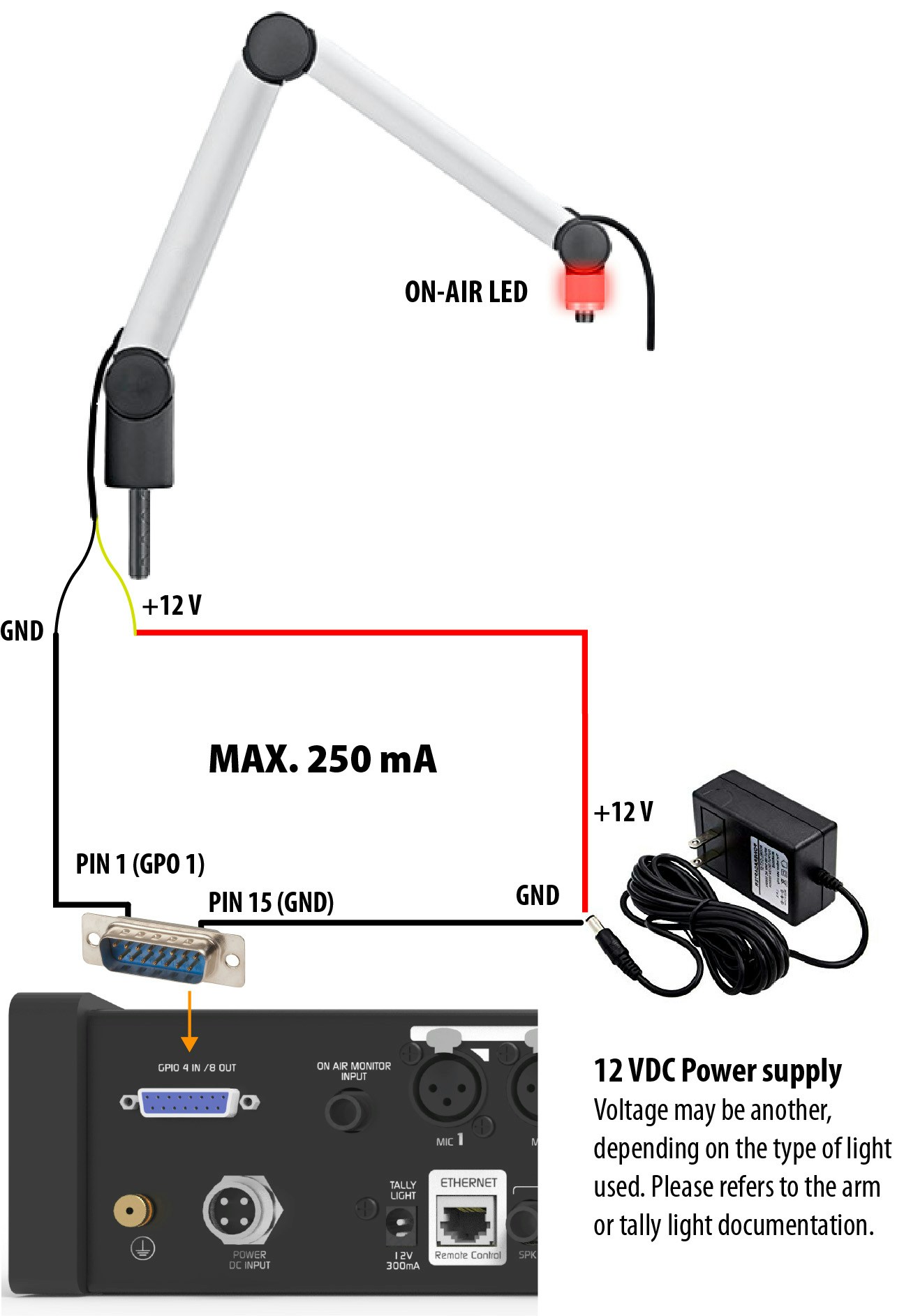
**GPO 1 to 7** outputs can work as **electronic switches**, switching LEDs connected to an external power supply, as long as current consumption does not exceed **250 mA**.
If current consumption exceeds **250 mA**, an **external relay** must be used for switching. It is recommended to use **GPO 8** to directly control a 12V relay coil with consumption up to 250 mA.
The figure shows an example of direct connection of a **microphone arm with LED**, using **GPO-1**.
**PIN 8** PROVIDES A FIXED VOLTAGE OF **+15 VDC / 100 mA** (max).
### ACTION CONFIGURATION
GPIO-triggered actions are defined in the `SETTINGS→GPIO` screen. Each **GP-IN** and **GP-OUT** can be associated with a channel and a specific action.
Available actions for **GPI** are:
`UNASSIGNED; CHANNEL ON/OFF; CHANNEL MUTE; MASTER MIC A`
Available actions for **GPO** are:
`UNASSIGNED; CHANNEL ON/OFF; TALLY A; TALLY B; TELCO RING`
**EXAMPLES**
\
The following GPI configuration: **GPI 1 | CHANNEL ON/OFF | CHANNEL 1**
...will make Channel 1 turn on or off according to the control signal present at **GPI 1** input.
The following GPO configuration: GPO 1 | CHANNEL ON/OFF | CHANNEL 6
...will change the state of **GPO 1** output according to Channel 6 being turned on or off.
## GPIO Application Cases
### LED Microphone Arm (GPO)
**GPO 1 to 7** outputs can work as **electronic switches**, switching LEDs connected to an external power supply, as long as current consumption does not exceed **250 mA**.
If current consumption exceeds **250 mA**, an **external relay** must be used for switching. It is recommended to use **GPO 8** to directly control a 12V relay coil with consumption up to 250 mA.
The figure shows an example of direct connection of a **microphone arm with LED**, using **GPO-1**.
 In the **GPIO configuration**, GPO outputs must be assigned to the ON/OFF function of the corresponding MIC channel.
Typical example:
* **GPO 1 →** ON/OFF MIC Channel 1
* **GPO 2 →** ON/OFF MIC Channel 2
* etc.
### Microphone Muting (using GPI)
**GPI** inputs allow executing automated actions on the console.
One of the most useful is temporary channel muting (MUTE), ideal for implementing a **cough button** in the studio. This allows the announcer to mute their microphone without operator intervention.
The following example shows the connection of a **momentary push button** to activate **GPI 1**.
In the **GPIO configuration**, GPO outputs must be assigned to the ON/OFF function of the corresponding MIC channel.
Typical example:
* **GPO 1 →** ON/OFF MIC Channel 1
* **GPO 2 →** ON/OFF MIC Channel 2
* etc.
### Microphone Muting (using GPI)
**GPI** inputs allow executing automated actions on the console.
One of the most useful is temporary channel muting (MUTE), ideal for implementing a **cough button** in the studio. This allows the announcer to mute their microphone without operator intervention.
The following example shows the connection of a **momentary push button** to activate **GPI 1**.
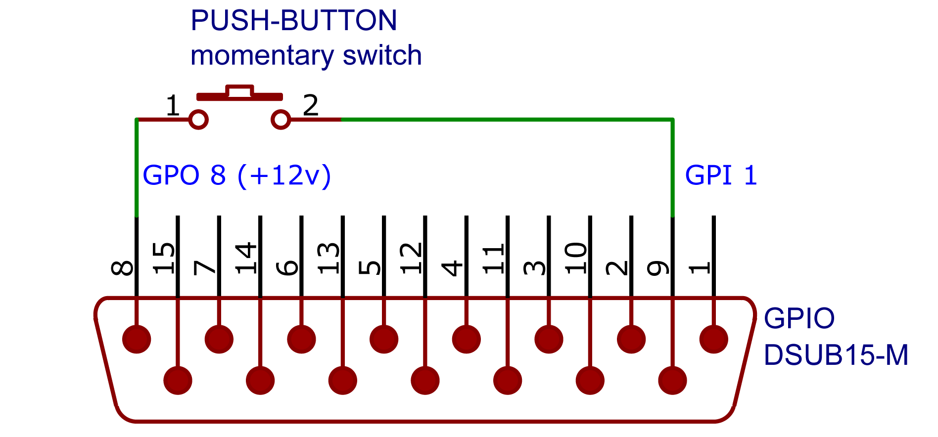 In this case:
* **GPI 1** is configured with the **MUTE** action and associated with the desired channel.
* **GPO 8** provides fixed voltage.
On UX24, configure GPO-8 for fixed voltage. On UX18 pin-8 always provides fixed voltage
During GPI-activated muting, if the operator **manually moves the fader**, the console returns control to them, and the microphone automatically returns to air.
## "ON AIR" Warning Lights (Tally Light)
On the console's rear panel, there is a **12V / 250mA output** for connecting **"ON AIR"** warning lights. The UX24 model has two outputs: Tally Light A and B.
* Up to **two Solidyne LA100 on-air lights** can be connected per output.
* For lights from other manufacturers, ensure total consumption **does not exceed 250 mA**.
The on-air light outputs are protected by a **PTC (fusistor)** component that acts based on temperature.\
If current exceeds **250 mA**, the output automatically disconnects to protect the console.
To restore the output:
1. Disconnect the load (the light).
2. Review the system to identify the cause of overconsumption (e.g. excess LEDs or short circuit).
3. Wait for the PTC to cool down before reconnecting.
In this case:
* **GPI 1** is configured with the **MUTE** action and associated with the desired channel.
* **GPO 8** provides fixed voltage.
On UX24, configure GPO-8 for fixed voltage. On UX18 pin-8 always provides fixed voltage
During GPI-activated muting, if the operator **manually moves the fader**, the console returns control to them, and the microphone automatically returns to air.
## "ON AIR" Warning Lights (Tally Light)
On the console's rear panel, there is a **12V / 250mA output** for connecting **"ON AIR"** warning lights. The UX24 model has two outputs: Tally Light A and B.
* Up to **two Solidyne LA100 on-air lights** can be connected per output.
* For lights from other manufacturers, ensure total consumption **does not exceed 250 mA**.
The on-air light outputs are protected by a **PTC (fusistor)** component that acts based on temperature.\
If current exceeds **250 mA**, the output automatically disconnects to protect the console.
To restore the output:
1. Disconnect the load (the light).
2. Review the system to identify the cause of overconsumption (e.g. excess LEDs or short circuit).
3. Wait for the PTC to cool down before reconnecting.