Power Supply
The unit is powered by an external switching power supply of 12 V / 1.25 A, provided from factory.Inputs and Outputs
The connection panel features two ¼” (6.32 mm) TRS jacks that provide, according to configuration:
- AUDIO IN: receives the audio sent to mobile phones, i.e., what the person on the other end of the line hears.
- AUDIO OUT: delivers the incoming signal from mobiles, i.e., the voice of the person on the other end of the line.
Configuration is done through six microswitches (dip-switch), whose function is indicated on the panel’s silkscreen.
Mode A – Connection to Solidyne Consoles
Solidyne compact consoles DX816/822, D612 and previous series 2300 and 2600 feature a dedicated External Hybrid connection, avoiding the use of line channels and auxiliary mix.| Dip-switch configuration |
|---|
| DSW 2 and 6: active DSW 4 and 5: active (conference) DSW 1 and 3: off |
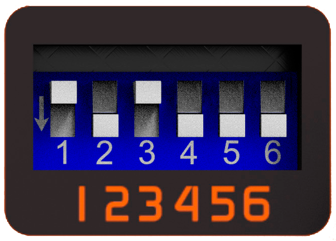 |

- BLT200 Output: not connected.
- BLT200 Input (AUDIO IN): becomes input/output. Connected with a standard TRS cable, factory provided.
- Tip: receives signal from console (adjustable with IN GAIN preset).
- Ring: sends A+B mix to console.
Conference against the console’s internal hybrid is also supported. The operator can talk privately with the lines in the same way as with the internal hybrid.
Mode B – Single Channel Connection (all consoles)
| Dip-switch configuration |
|---|
| DSW 2: active DSW 4 and 5: active (conference) DSW 1, 3 and 6: off |
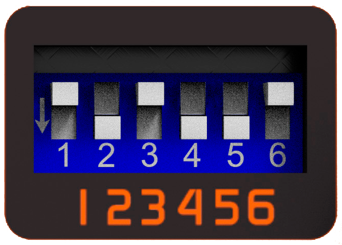 |

- BLT200 Output: delivers A and B signals mixed on tip. Ring remains disconnected.
Connected using the included “Y” breakout cable (TRS to TS), using only the tip plug; or using a simple TRS cable. - BLT200 Input: receives signal on tip, connected to a console output with the included TRS cable.
Ensure DSW 6 = OFF.
Otherwise BLT200 output will be connected to console output.
Otherwise BLT200 output will be connected to console output.
An auxiliary mix bus (mix-minus) is required to send to BLT200 the signal that the caller will hear.
Local microphones must be sent, but never CEL-A and CEL-B signals that enter mixed to the console, to avoid feedback.
In conference, A and B levels are adjusted from BLT200’s panel. The operator can talk privately with the phones by activating PFL on the corresponding channel and using a microphone assigned to the auxiliary mix.
Mode C – Dual Channel Connection (all consoles)
| Dip-switch configuration |
|---|
| DSW 1: active DSW 4 and 5: active (conference) DSW 2, 3 and 6: off |
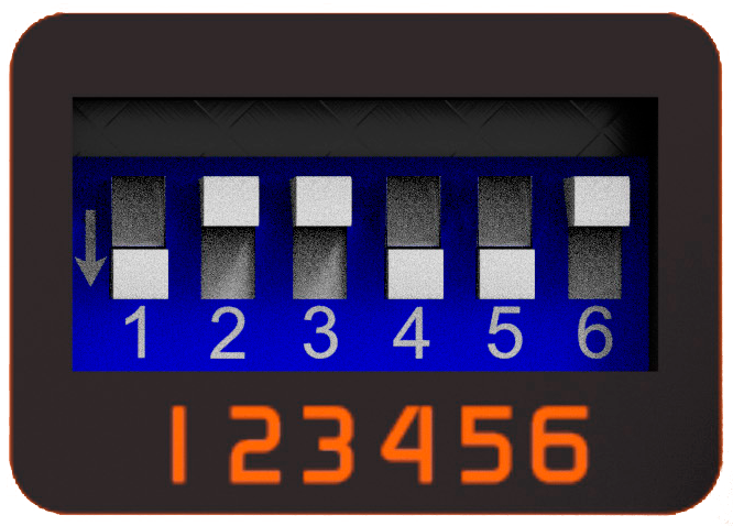 |

- BLT200 Output: delivers A and B signals separately (tip = A, ring = B).
Connected to two console inputs using the provided “Y” cable (TRS to 2 × TS). - BLT200 Input: receives signal on tip, connected to console’s auxiliary output using the provided TRS cable.
Ensure DSW 6 = OFF.
Otherwise BLT200 output will be connected to console output.
Otherwise BLT200 output will be connected to console output.
An auxiliary bus (mix-minus) is required. Local microphones are sent to the mix, but not BLT200’s A and B signals.
The operator can talk privately with each mobile by activating PFL on the corresponding channel.
Mode D – Dual BLT200 (4 mobiles)

- BLT200 Outputs: connected to two console inputs using TRS cables.
- BLT200 Inputs: connected to a console auxiliary output using a TRS to two TS “Y” breakout cable (provided).
Ensure DSW 6 = OFF.
Otherwise BLT200 output will be short-circuited and there will be no audio.
Otherwise BLT200 output will be short-circuited and there will be no audio.
Conferences
Conference activates internal cross-return, allowing phones to hear each other when two lines are simultaneously on-air.| DSW 4 and 5 ON: conference enabled. DSW 4 and 5 OFF: no conference (mobiles can be on-air simultaneously but won’t hear each other). |
|---|
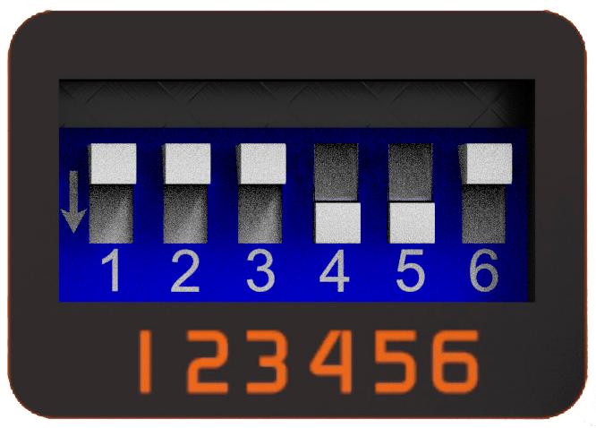 |