Available streaming types
- Streaming 1 (outgoing)
Uses RTP protocol, ideal for transmitter site link (STL). - Streaming 2 (outgoing)
Compatible with Shoutcast/Icecast servers for internet broadcasting. - Streaming 3 (incoming)
Can be RTP or public HTTP streaming.
When enabled, the received audio is automatically decoded and switched, replacing the AES-1 input.
Signal source and send level
Streaming uses the PROGRAM signal taken from AES-1 output, both for Icecast/Shoutcast server upload and RTP audio stream. The default output level (gain=0) is -20 dBfs referenced to 0VU (1 kHz @ 0VU = -20 dBfs).Gain is adjusted from SETTINGS → OUTPUTS screen.
Streaming services configuration
It’s done from the SETTINGS screen under STREAMING option.It shows four tabs to configure outgoing streaming services (UP-STREAM and RTP Link); incoming (DOWN-STREAM) and network options.
UP-STREAM (TX)
The UP-STREAM tab allows configuring an Icecast or Shoutcast broadcast server to publish the program signal.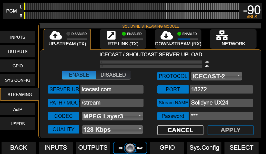
UP-STREAM Icecast/Shoutcast
- ENABLE/DISABLED: Enables or disables streaming transmission when changes are confirmed by pressing APPLY.
- PROTOCOL: Defines if server is Icecast or Shoutcast type.
- SERVER IP: Server destination IP address.
- PORT: Server TCP listening port.
- MOUNTPOINT: Unique name that identifies the stream on the server.
- Stream NAME: Name that identifies the stream.
- CODEC: Transmission audio format (Opus or MP3).
- QUALITY: Bitrate for encoding
- PASSWORD: Access password for publishing (if applicable).
- APPLY: Applies and saves changes and starts or stops transmission (according to ENABLE/DISABLED status).
Configuration parameters for Icecast/Shoutcast are provided by the server provider.
RTP LINK
The RTP LINK tab allows configuring streaming transmission to a specific IP address, for example, to send the program signal to a transmitter site (STL).
- ENABLE/DISABLED: Enables or disables RTP streaming when changes are confirmed by pressing APPLY.
- DESTINATION ADDRESS: Destination IP address.
- PORT: TCP transmission port.
- CODEC: Audio format for RTP (PCM / MP3).
- QUALITY: MP3 bitrate or PCM sampling rate.
-
GPO: Enables sending on-air light (Tally Light) signals via TCP/IP for compatible Solidyne equipment.
- Studio A and B (lines 1 and 2 respectively)
- Studio B and A (reversed order)
- A+B (signal activates on both lines, regardless of active studio)
Down-Stream (RX)
Allows configuring an incoming stream. When DOWN-STREAM module is activated (ENABLE), the decoded audio is internally routed to AES-1 input, which changes its name to STREAM-1.In this mode, the AES-1 connector on the rear panel is disabled.
-
RUN/STOP
Starts or stops streaming decoding when changes are confirmed with APPLY. -
PROTOCOL
Defines the incoming stream type. The following formats are supported:- Public HTTP and MMS streams encoded in PCM 16 (44.1/48 kHz), MP3 or Opus.
- RTP streams in PCM 16 (44.1 kHz) and MP3.
-
SERVER URL/IP
Name or IP address of the server generating the stream. -
PORT
TCP port where the stream enters.
Default value: 0. -
MOUNTPOINT
Unique name that identifies the stream. -
APPLY
Applies configuration changes.
Step by step Download a step by step guide to configure an incoming stream.
Network (Streamer Module)
General network settings for the UX24 Streamer module (not to be confused with web control access).