

UX18 Main Panel Zones and Controls
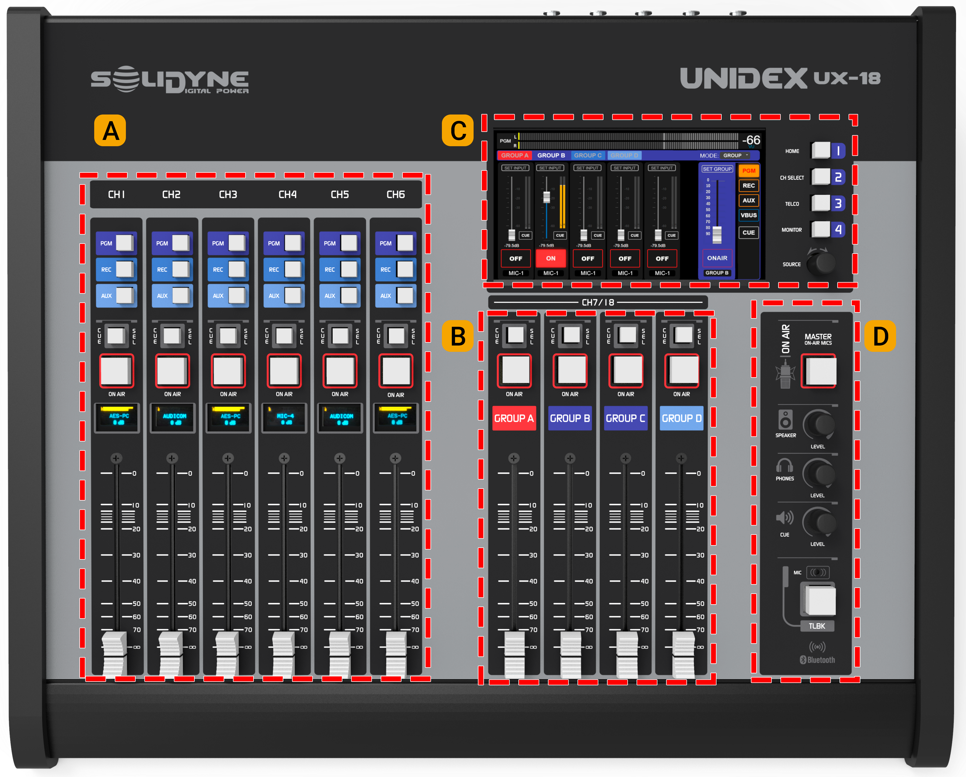
Traditional controls with faders, assignment buttons, on-air, and pre-fader listen (PFL).
They operate conventionally and allow direct handling of line communications, VoIP, and Bluetooth cell phones (via UDX TELCO adapters). B — Groups
4 GROUPS handle channel sub-mixes. Channels 7 through 18 can be assigned to the groups. Each group’s sub-mix is controlled from an on-screen mixer that appears by pressing the GROUPS shortcut. C — Touchscreen
A 7” screen used to operate multiple console functions. Includes 4 contextual quick-access buttons and a rotary encoder with push button. D — Monitoring and Intercom
Area dedicated to monitoring control and the talkback circuit.
Main Screen
Level Meters
The PGM, REC, AUX, and VBUS meters display:- Average level in VU (slow-moving blue bar).
- Peak level in dBFS (floating yellow segment).
The numeric value on the right shows the current maximum (in VU or dBFS) and toggles by tapping on the number.
The main meter remains visible on all screens and the bus can be changed by tapping the bus name on the left.
CUE Level
Displays the CUE bus level, after the physical level knob.Status
- Unidex IP: IP address for remote control. Enter it in a web browser (recommended: Google Chrome) to access the control interface. Requires connection of the Ethernet Remote Control port to the LAN.
- Stream IP: IP address of the streaming module. Enter it in a browser to configure streaming services. Requires connection of the Ethernet Streaming port to the LAN.
- SCENE: Name of the currently active scene.
- USER: Active user profile (ADMIN, EXPERT, or BASIC).
- MSG: System messages.
- ”+” Advanced: Opens maintenance options (includes shutting down the internal CPU before cutting power).
Main Clock
Displays the current time.It synchronizes automatically if the console is connected to the Internet, or manually (see SETTINGS -> SYS CONFIG screen).
ON AIR Counter
Starts an ascending count (hh:mm:ss) when microphones are activated. When they are turned off, the value remains on screen.Quick-Access Buttons
4 buttons located to the right of the screen provide quick access to main functions.- HOME Calls up the main screen.
- GROUPS Displays the group assignment and sub-mix controls.
- TELCO Interface for managing channels assigned to telephone lines and Bluetooth phones.
- MONITOR Displays the audio source assignment for the Studio and Control Room. Contains advanced functions related to speaker and headphone monitoring.
MENU on the Main Screen
Shortcuts on the main screen:- SETTINGS: Advanced and system configuration (ADMIN only).
- SCENE: Scene and user profile management. Also includes the CHANNEL MAP wizard.
- PROCESS: Access to equalization, compression, de-esser, and noise gate.
- VIRTUAL: Accesses the virtual channel control screen. When a virtual channel is active, VIRTUAL flashes in red.
- CHANNEL: Information and control of the selected channel, including gain, panning, processors, and source reassignment.
Power saving mode Screens turn off after 15 minutes of inactivity. They reactivate by moving a fader or pressing an Intercom button.