FM Tuner
The internal FM tuner enables measurements of the received radio signal.Access it from the SETUP side menu, under FM RECEIVER – ANALYZER.
- Usually the tuned station is the same one where the processor operates.
- Any other station can also be tuned to view its parameters.
Tuner Controls
- ON/OFF → turns the FM tuner on or off.
If reception is very poor, the unit turns off automatically. - FREQ → enter the station frequency (MHz, use decimal point, e.g. 95.9).
- Type the value using the keyboard and confirm with ENTER.
- If it was off, the tuner turns on.
Reception Parameters
- Reception Quality: Reception validity indicators:
- Show if signal quality allows reliable measurements.
- Otherwise, out-of-range variables are displayed: RF low level, Multipath, Noise, Adjacent channel interference.
- Reception quality depends on the connected antenna.
(See FM Receiver Antenna section). - RF LEVEL → RF signal level at antenna. Must be > 40 dB.
- Multipath → distortion percentage due to reflections. Must be < 10%.
- Band Type → FM band type according to region.
- RBDS Mode → activates RBDS system (RDS version used in USA).
DIAL SCAN
Tool that scans the FM band in 100 kHz steps and generates a graph showing signal strength for each detected station.
Transmission Analysis
FM Measurements
Monitoring of parameters measured on the tuned signal: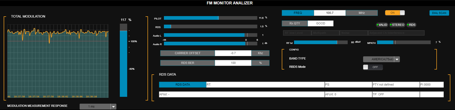
- TOTAL MODULATION → FM modulation level measured on the tuned signal.
- MODULATION MEASUREMENT RESPONSE → measurement integration time:
- Instantaneous
- 125 µs (recommended for peak)
- 250 µs
- 500 µs
-
1 ms
Appropriate integration depends on regional standards.
- PILOT → pilot tone modulation % (default: 9%).
- RDS → RDS subcarrier modulation % (default: 4%).
- AUDIO L/R → audio level (dBFS).
- CARRIER OFFSET → carrier deviation (kHz).
- RDS BER (bit error ratio) → RDS data quality.
- 0% = no errors.
- 100% = unreadable data.
- RDS DATA → RDS transmitted texts.
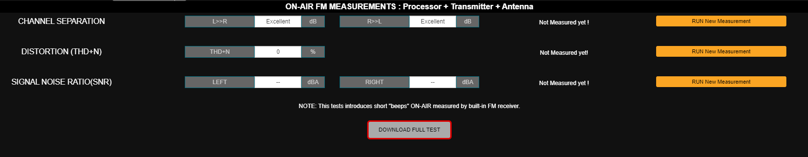
Channel Separation, Distortion and SNR
The system measures:- Channel separation.
- Total harmonic distortion + noise (THD+N).
- Signal-to-noise ratio (SNR).
- Can be done remotely without interrupting transmission.
- During the process:
- A very brief audible tone is injected (~250 ms).
- For SNR, the on-air signal is muted for 2 seconds.
- Click the RUN new measurement option shown to the right of the parameter.
- This executes the measurement for that parameter and displays the result.
Separation can be optimized from the stereo encoder advanced controls.
See Channel Separation Measurement and Adjustment.
See Channel Separation Measurement and Adjustment.
Technical Transmission Report
- The DOWNLOAD FULL TEST button runs all measurements and generates a text file with results, including FM Analyzer values.
- The file is saved to the browser’s downloads folder.
- This report can be sent to Technical Support for remote diagnosis.
- If the tuner is off, reports cannot be generated. To turn it on: press ON/OFF and wait for values to stabilize.